Whipple Installed!

Crazy part is the sensor is only used for pre-charge air temperature reading, it doesn't even input boost into the PCM....Hopefully Whipple get's back to you.

Really, they should have overnighted the part to you first phone call.

I have now discovered I am missing the spacers to mount the IC as well, I emailed them about that, and still not a peep from Whipple. tuesday afternoon....

I have my mom coming tomorrow to help get kids to soccer practice. Truck has been down since Friday.
 
For anyone else doing this install or contemplating it. INVENTORY each and every piece by part number and location before you touch your truck. Pull out the tomahawk device update everything download your stock tune and send it to Whipple or any other tuner. Avoid delays at all cost. I bench installed mine so many times before the date came to do it I really didn't need the directions much. I feel like every couple of days I went through withdraws not looking at the Whipple & it sat next to my tool box for like 2 weeks.
If you supply a shop with the kit have them inventory it before you schedule a drop off time for the work. Or if you purchase through a shop same same. Demand a pre inventory and check list with the tech. As a tech I would not mind this one bit, especially on something as exciting as this for the end user.
 
For those that have the Procharger Pinning kit. These are the instructions for pinning taken from the Procharger kit installation manual. Hope it helps.

Procharger Pinning Kit.webp
 
Finally heard from Whipple, they are sending me the T MAP bag, the 4 spacers, and a new intercooler.
 
For those that have the Procharger Pinning kit. These are the instructions for pinning taken from the Procharger kit installation manual. Hope it helps.

View attachment 229169

I liked how the kit I got was 2 pins. Seems like it would be better for balancing.

Although, the bit started getting real tired halfway through the second hole.
 
Tracking for replacement parts says they will get here Tuesday.
 
Any of you who previously installed know what to do with this? The brake booster instructions differ from my truck. I have an extra canister with an electrical plug that the directions never mention.

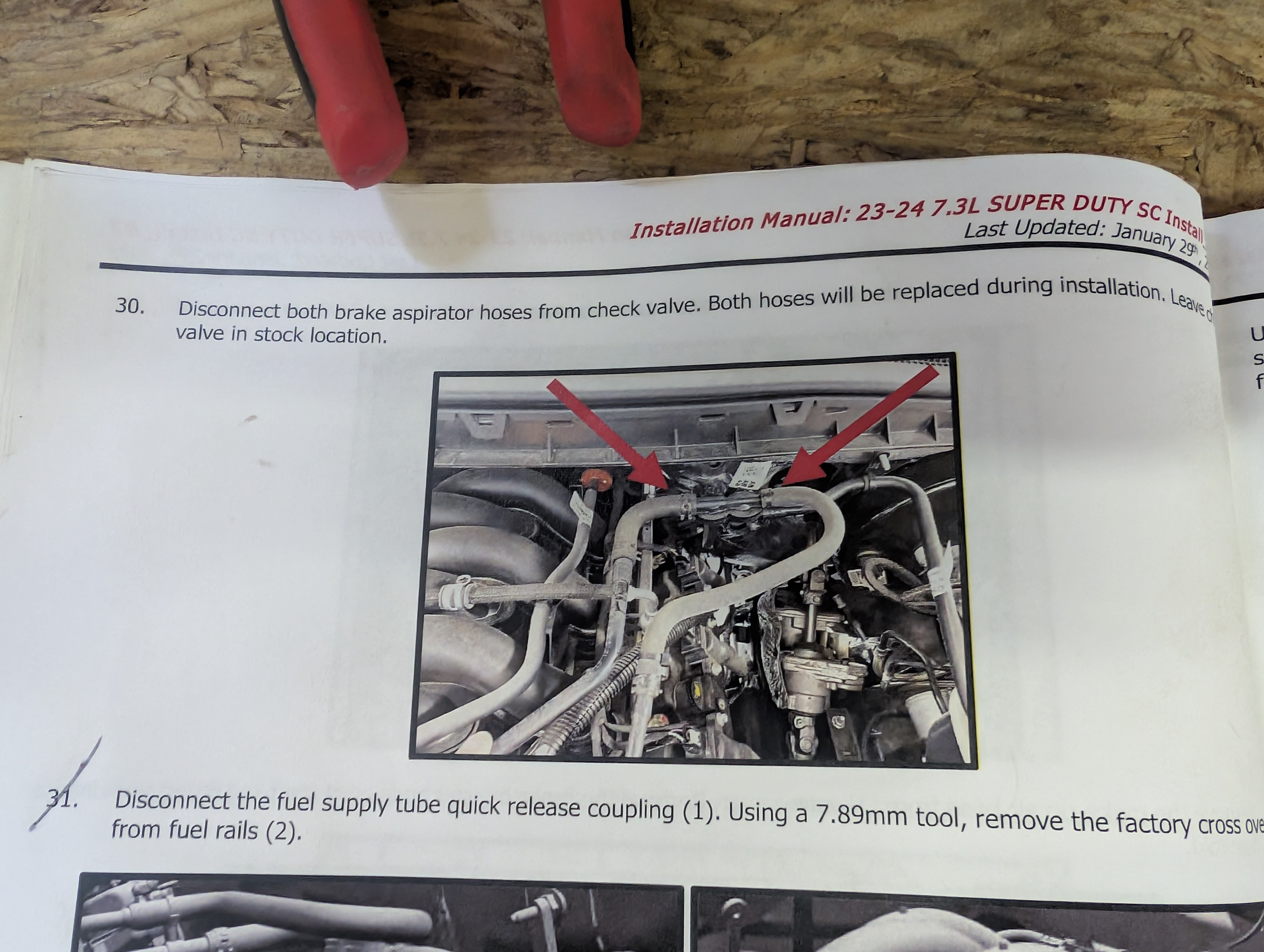
Here is the un-install step:

iRGKx1t.jpeg


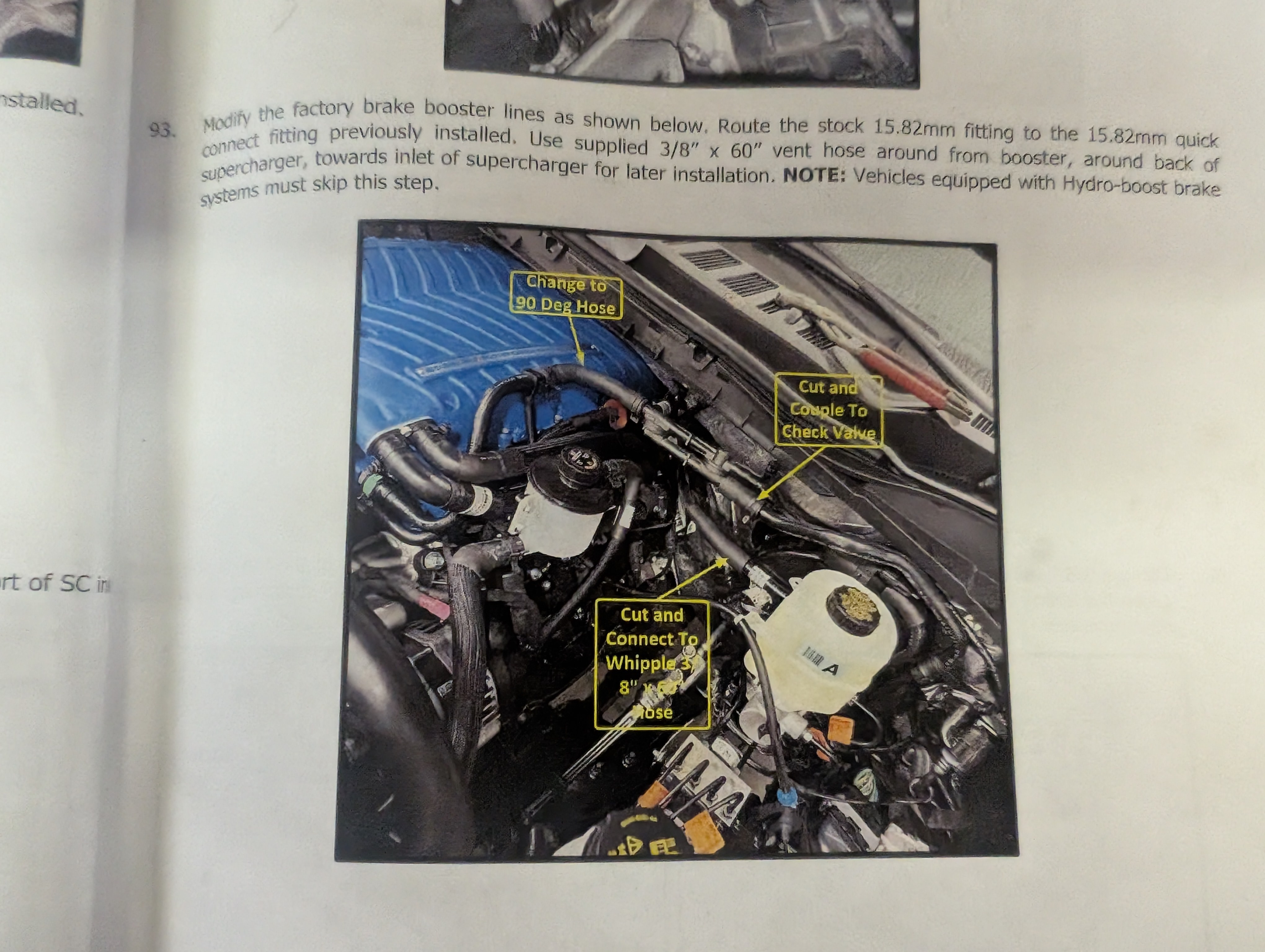
This is the install step:

8NB5uuE.jpeg


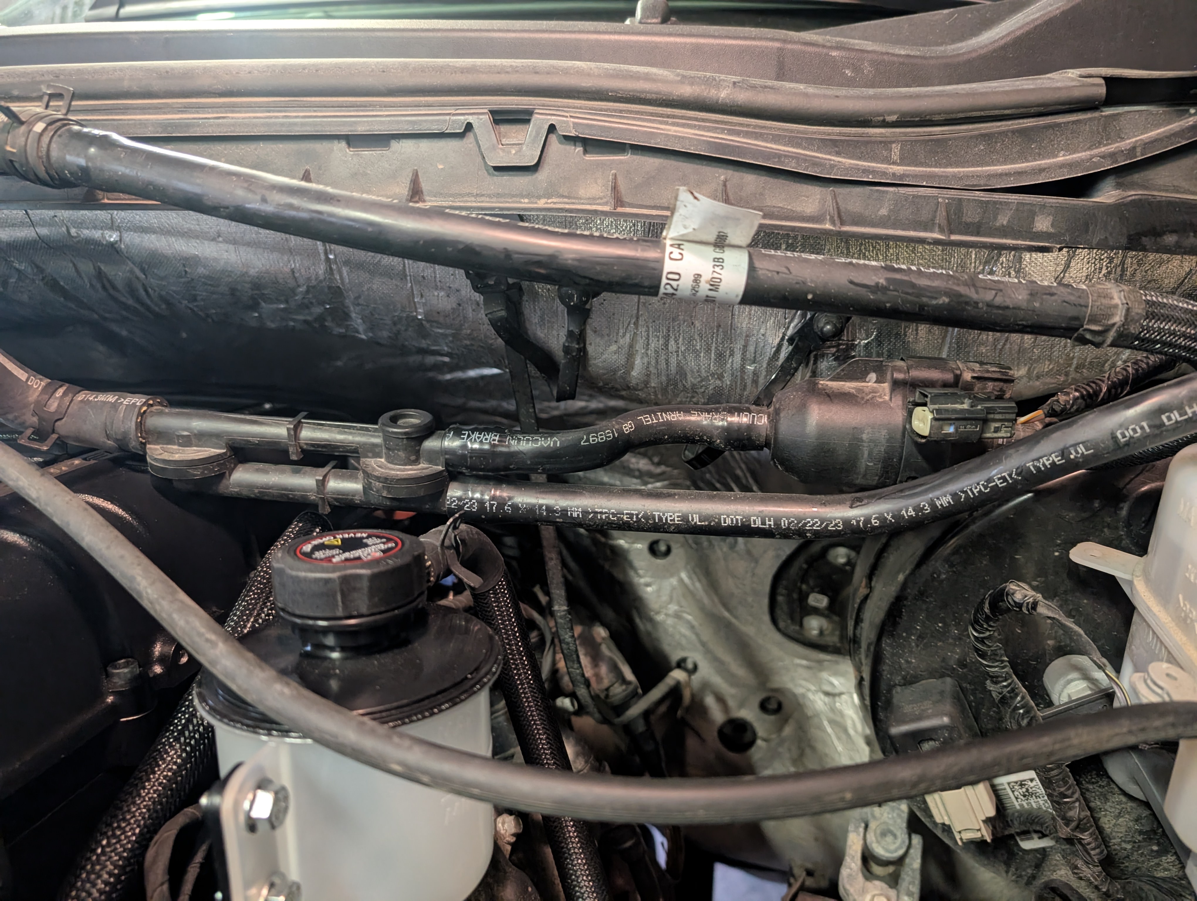
And this is what mine looks like:

EGBMJii.jpeg


Do I just remove it and tape up the plug?
 
Would have to be a newer model mine does not have this.
Yup, mine is a '23.

I have emailed Whipple as well.

Tracking says my missing parts should arrive today!!!!
 
That whole are is quite confusing and I can't really tell what's going on.

All I have left is mount and plumb the heat exchanger, install the T MAP, wire the pump, put the front back together, and flash the ECU! Well, and figure out that brake line issue.
 
Heard from Whipple:

The pictures in the instructions are re using the factory hoses but I didn't like how they looked with that check valve sitting next to the supercharger and we updated them but it looks like the instructions still need to be changed I apologize.

The factory 90* rubber hose I reused with the factory 15.82mm fitting with the plastic vauum port in the middle of the 2 pieces

You will then connect that to the check valve on the side with 1 port

You will then take the short hose with the 180* bend and attach that to the check valve port that is in line with the hose on the single port side of the check valve and that will route up to the pressure sensor mounted on the firewall

And for the last port on that check valve you will use the hose with the 180* bend and 15.82mm fitting and connect it to that last port and that will run over to your brake booster

And finally the last hose in that bag will run from the driver side port on the sensor mounted to the firewall and back behind the supercharger and up to the fitting in the air tube
 
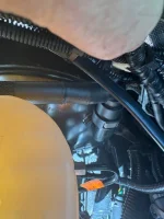
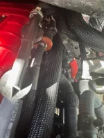
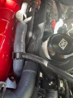
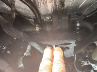
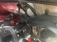
I have a 24, and this was my biggest hang-up during the install. I got pictures sent from Whipple, but I'm not sure if you can make out how to set this up from my pictures. I did it back in May, so I have forgotten the particulars about the exact routing.
 

Attachments

  • IMG_7246.webp
    IMG_7246.webp
    52.6 KB · Views: 28
  • IMG_7245.webp
    IMG_7245.webp
    37.7 KB · Views: 26
  • IMG_7244.webp
    IMG_7244.webp
    58.6 KB · Views: 21
  • IMG_7243.webp
    IMG_7243.webp
    48.3 KB · Views: 24
  • IMG_7241.webp
    IMG_7241.webp
    55.8 KB · Views: 20
  • IMG_7242.webp
    IMG_7242.webp
    66 KB · Views: 23
  • IMG_7240.webp
    IMG_7240.webp
    66.4 KB · Views: 24
  • IMG_7239.webp
    IMG_7239.webp
    45 KB · Views: 18
  • IMG_7238.webp
    IMG_7238.webp
    48.8 KB · Views: 22
Bummer. I am pretty sure for my 2022 the MAP sensor is CX-2519. This has supposedly been supersceded by CX-2760. It may be easier for Whipple to confirm this is the correct PN vs trying to look it up. You would think a nearby dealer would have one in stock.

CX-2760 is the current Motorcraft part number that supersedes CX-2519. This is a Manifold Absolute Pressure (MAP) Sensor, also known as a Turbocharger Boost Sensor, used in various Ford vehicles like the F-150 and Edge from model years around 2015 onward. It replaces earlier numbers including CX-2486, CX-2494, CX-2519, CX-2657, DV2Z-9F479-B, DV2Z-9F479-C, DV2Z-9F479-D, GV2Z-9F479-D, and PV4Z-9F479-A. The chain of supersessions for CX-2519 goes through PV4Z-9F479-A before reaching CX-2760.
I believe what I got was a CX-2519
 
I have a 24, and this was my biggest hang-up during the install. I got pictures sent from Whipple, but I'm not sure if you can make out how to set this up from my pictures. I did it back in May, so I have forgotten the particulars about the exact routing.
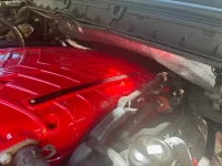
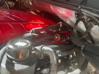
Thanks, that does help, I think I can get it now. That red looks great!!!!!!!!!!!!!!!!!!!!!!

My parts came today so I should be able to finish this up
 
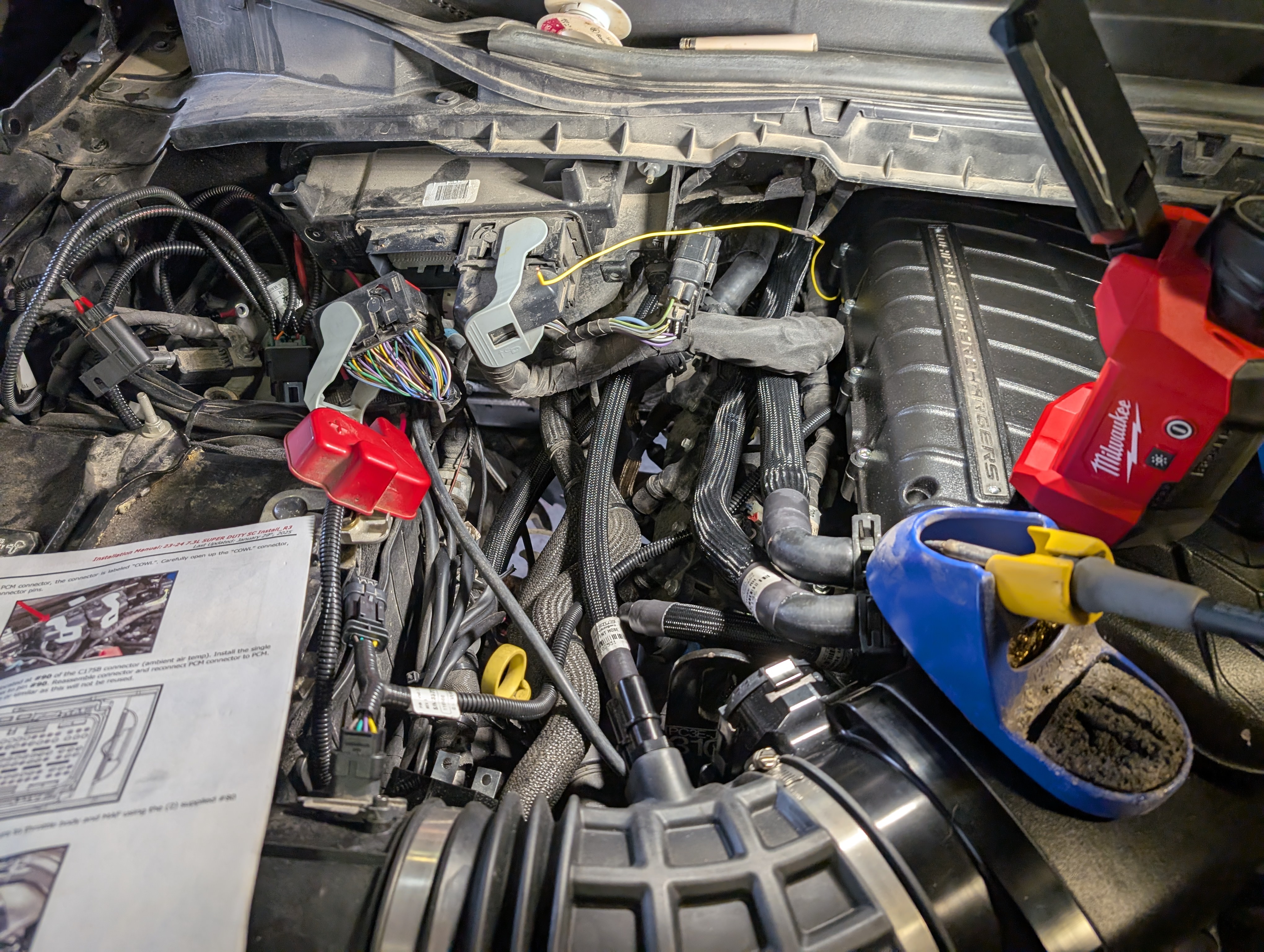
Can anyone confirm that the single yellow wire from the MAP/MAF that goes to the PCM connector pin 90 replaces the original wire going to pin 90? I dont understand why you need to de-pin it if youre changing the wire, can I just cat and solder the wire and avoid depinning, where Ill cut the wire anyway?

Like 3 steps left!
 
Poked around over lunch and got the electrical connections finished! Now I just need to re-assemble the front end, burp the coolants, and flash the tune!

Cut and soldered the wire instead of depinning it.

j69VGU5.jpeg
 
Back
Top Bottom