
Upfitter Wiring Harness Discussion

Sorry, this is misleading. You can hook directly to the battery; it will not make any difference on the computers ability to monitor "battery health" which is what this statement is all about. Here's why:

*The BMS gets its information from the current sensor, also known as the Hall effect device, which is a device that measures a field around a wire to determine how much current is flowing and the direction it is flowing. (charging or discharging) It is essentially the heart of the monitoring system for the electrical charging system health. It can determine if the charge system has a fault based on how much current is drawn during operation. (With ignition on and running)

*If you have a 6.7, you have two batteries, (Or dual battery option in gasser) both batteries using Black/Violet wires to ground, ~1/0 gauge. Both are attached directly to the chassis/engine, and one smaller lead ~10 gauge, parallel on the passenger side battery, running through a Hall Effect device to monitor current draw or charge current, during operation. (Engine running) The two larger wires represent a shunt; the smaller wire is the measurement plane for the current sensor. also connected to the chassis in parallel with the two larger wires in parallel. (See schematic for visual) Heavy current flows through the large wires, a small current flows through the small wire in parallel, most likely "calibrated" to some extent to determine the current flow of the system.

*Heavy current devices are connected directly to the battery such as a winch, and perhaps some accessories like a plow, not to the chassis. They are not monitored by the current sensor.

*If your truck is not running, you can still use the battery functions like a winch, PTO, lights, etc., and the computer is not in play.

*Hooking up a high current accessory draws its current through additional wire in series if hooking up through the chassis to battery connection, essentially dropping voltage in the wires, thereby reducing the voltage at the device. (The wires essentially become resistors at high current draw.)
To avoid this occurrence, a device such as a winch is directly connected to the battery. (Here's a video of A-Rod installing a winch in a 23 YM, the wires are directly connected to the battery.
(Skip to 51:00 minutes to see hook-up) There is no ill effect of hooking directly to the battery.

Ok, so reading the manual is always a good thing. But understanding what and why it is printed, is also essential. So why does the manual make this statement? The batteries and charge system are monitored for health over time and as maintenance to determine charge/discharge. As batteries age, they may suffer with less capacity. The computer can possibly tell when the batteries are deteriorating via the sensor (hall effect device) and determine if a battery needs to be replaced or malfunctioning. It assumes that if you draw directly from the battery, the BMS cannot determine if there is an issue with the charging system.

By the way, as a side note, there is a lot of evidence that this does not work so well. How many people have had two batteries in parallel, getting error codes, just to find out one of the batteries were low or dead when measured independently.

If the BMS does not know how much current is drawn it can't determine the health of the batteries. (Supposedly) The fact is, you can draw all kinds of current with the ignition off, start the truck, and it will replenish, and the computer won't care. But if you kill the battery, all bets are off as to what it will do.

If you add up all of the accessory current capabilities of the upfitter switches, it's a whopping 180A+ capacity. Not to mention you can add a relay and draw even more. In this case, there is no difference if you hook accessory grounds to the chassis or the battery, it is still going to draw current from both batteries and the alternator (s) will supply the necessary current required for high demands via the regulators.

The second part of the paragraph is also telling, In quotes:
"Note: If you add electrical accessories or components to your vehicle, this may adversely affect battery performance, durability, and the performance of other electrical systems on your vehicle."

Yes. Absolutely true. If the battery is drawn down, the BMS won't work right, you can cause irreparable damage to the batteries, the loss of voltage can cause the tranny to "relearn", etc. May even throw a code. But this is not the fault of the common or chassis ground, it is a fault of the battery going dead due to inability to keep up with the demand. If you run a winch and kill your battery, you will have the same issue. And the statement is assuming the BMS will read and prevent this.
Not if the engine isn't running. And certainly not in the case where a winch is in operation.

The statement is really misleading. It's all about the battery monitoring system. I really wish tech writers could clarify this stuff. You notice they don't mention the winch.

Here's a schematic of the current sensor with a single battery and the schematic of our trucks to the right. Note the difference in the ground and chassis ground connections. The chassis ground is terminated at the engine with the common ground through two large wires. Essentially the same electrical point. It will make little or no difference whether the device is hooked up to the chassis or the battery post.

View attachment 202149

Hope I didn't miss anything. It's late... :unsure:
just seeing this and i have a question about your post...

On my 2022 (single battery) there is a current transformer-looking device NOT the device in A-rod's video. If I have a completely stock wiring setup and i wire my winch to the chassis for ground and then wire the hot to the positive post then the flow will be measured by the device because all wires connected to the negative go through said device. This makes sense, not questions here

However,

If i wire the negative from the winch directly to the battery post and DONT run it through said device... you're saying that is the same as the chassis ground and it'll still be measured by the device?

Could you walk me through how thats possible?
 
Thanks Guys, I have no problem disconnecting the battery. It looks so much easier in the video to add the Upfitter wires purchased here with the Upfitter fuse box out.
Perhaps it is, but it’s also easy to add the upfitter wires without fully removing the fuse box. That’s what I did. I just temporarily zip-tied it out of the way, made the connections, and then snapped the box back into place.
 
Anybody installed this on a 2025 F-250 ?

Also, please let us know when you start up the next waiting list.

Thanks
 
Perhaps it is, but it’s also easy to add the upfitter wires without fully removing the fuse box. That’s what I did. I just temporarily zip-tied it out of the way, made the connections, and then snapped the box back into place.
Where did you end up going with the ground? I haven’t installed yet but did plane to do what you did.
 
just seeing this and i have a question about your post...

On my 2022 (single battery) there is a current transformer-looking device NOT the device in A-rod's video. If I have a completely stock wiring setup and i wire my winch to the chassis for ground and then wire the hot to the positive post then the flow will be measured by the device because all wires connected to the negative go through said device. This makes sense, not questions here

However,

If i wire the negative from the winch directly to the battery post and DONT run it through said device... you're saying that is the same as the chassis ground and it'll still be measured by the device?

Could you walk me through how thats possible?
Thanks for the question. Sorry for any confusion, I did make an error in my original description, there are TWO wires going through the Hall device. This has no bearing on your question though.

The direct answer to the question is: No, I'm not saying the device will make this measurement. Quite the opposite, it will indeed NOT make this measurement. But it will not make any difference to the BMS as the configuration for a winch or any other high current accessory is outside of the basic configuration. Drawing heavy current through the chassis wiring may not be adequate for full efficiency. I'll explain.

The chassis and common ground are "electrically" the same point with no current flow. What that means is that the resistance between the two is essentially zero ohms with no current flow, albeit there is resistance in this wire affecting the drop under heavy draw. Where this comes into play to distinguish the difference is when there is a current flow to any component in the vehicle, the sensing device (the transformer looking thing) that measures the current flow from the battery post (common ground) to the chassis, (typically, the engine) there is a field developed in the wire creating a sensed voltage in the sensor that can be read by the BMS. Under normal conditions with no winch hooked up, this configuration allows the BMS to measure the current flow from the battery to the vehicle, or the charge current in the opposite direction. This is needed to determine health of the charge system. Nowadays they use the Hall sensor instead of a direct connection, higher technology and a much more accurate result.

Think of the old ammeter in older vehicles. The current flowed through a shunt (Sometimes a resistive wire) and the ammeter measured the voltage drop across the calibrated shunt, then did a calculation to determine how much current was flowing. (I=E/R or for those new engineers, I=V/R ;)) The meter generally read in an "AMPS" scale. (Typically, 20 or 40A full scale) On some really old cars, the shunt was actually part of the meter; a potentially bad situation if the meter was to short out and cause a fire. Ask me how I know this...)

The single battery connection is through the Hall sensor and current is measured as it flows to the chassis and engine starter motor. On a dual battery setup, Diesel or gas) only one battery is monitored by the sensor. I would imagine that the total current draw would be calculated as two batteries in parallel will be drawn "equally" and could do the calculation for total draw. It's hard to visualize the connections for electrical flow because most current flows through the path of least resistance. But the measuring method only measures one leg.

The third wire in the two-battery or single battery setup is the mystery. There is a small gauge wire that parallels the negative wire; both go through the hall sensor, and both will be measured and accumulated as the total current draw. This gets confusing because in theory, one wire should do the job. But the small wire simply attaches to the chassis while the major ground wire attaches to the engine. The heaviest draw in the system is the starter. But this is essentially not the same point as the chassis under heavy current draw, and there may be additional paths where the current can flow or cause impedance. (Mesh connectors from chassis to frame, etc.) The total current flow and paths are likely calculated in design.

Now for the winch and heavy current devices.

The more current a device needs, the less resistance you want in the path. All of the wires aforementioned are resistive paths for the winch and other heavily drawn devices attached to the chassis, so ideally you want them connected direct to the battery and avoid all the extra wire paths. This not only gives the winch more juice at the connection, but it also avoids drawing all that current through lesser wires with a potential to burn them out.

Accessories draw relatively little current, and they have little or no impact on the overall scheme of battery maintenance monitoring. Not to mention that some people run a set of lights and others cover their vehicle in lights ...and refrigerators, air pumps, train horns, etc. No two systems are the same. The BMS can't determine what's right or wrong in this case. So, the reality is, it doesn't matter where you terminate them, the system will keep up via the alternators and you will only run into problems when the amount of current exceeds the capability of the stock wiring. Hence, heavier wire direct connected to the battery post for heavy current scenarios.

Every accessory manufacturer has their own recommendations on hook-up. A simple rule is to follow the manufacturers advice, and you won't go wrong. But the theory is as old as the discovery of electricity itself. Simple laws apply the same now as they have always. Just keep in mind, current wants the least amount of resistance possible for maximum efficiency.
 
Thanks for the question. Sorry for any confusion, I did make an error in my original description, there are TWO wires going through the Hall device. This has no bearing on your question though.

The direct answer to the question is: No, I'm not saying the device will make this measurement. Quite the opposite, it will indeed NOT make this measurement. But it will not make any difference to the BMS as the configuration for a winch or any other high current accessory is outside of the basic configuration. Drawing heavy current through the chassis wiring may not be adequate for full efficiency. I'll explain.

The chassis and common ground are "electrically" the same point with no current flow. What that means is that the resistance between the two is essentially zero ohms with no current flow, albeit there is resistance in this wire affecting the drop under heavy draw. Where this comes into play to distinguish the difference is when there is a current flow to any component in the vehicle, the sensing device (the transformer looking thing) that measures the current flow from the battery post (common ground) to the chassis, (typically, the engine) there is a field developed in the wire creating a sensed voltage in the sensor that can be read by the BMS. Under normal conditions with no winch hooked up, this configuration allows the BMS to measure the current flow from the battery to the vehicle, or the charge current in the opposite direction. This is needed to determine health of the charge system. Nowadays they use the Hall sensor instead of a direct connection, higher technology and a much more accurate result.

Think of the old ammeter in older vehicles. The current flowed through a shunt (Sometimes a resistive wire) and the ammeter measured the voltage drop across the calibrated shunt, then did a calculation to determine how much current was flowing. (I=E/R or for those new engineers, I=V/R ;)) The meter generally read in an "AMPS" scale. (Typically, 20 or 40A full scale) On some really old cars, the shunt was actually part of the meter; a potentially bad situation if the meter was to short out and cause a fire. Ask me how I know this...)

The single battery connection is through the Hall sensor and current is measured as it flows to the chassis and engine starter motor. On a dual battery setup, Diesel or gas) only one battery is monitored by the sensor. I would imagine that the total current draw would be calculated as two batteries in parallel will be drawn "equally" and could do the calculation for total draw. It's hard to visualize the connections for electrical flow because most current flows through the path of least resistance. But the measuring method only measures one leg.

The third wire in the two-battery or single battery setup is the mystery. There is a small gauge wire that parallels the negative wire; both go through the hall sensor, and both will be measured and accumulated as the total current draw. This gets confusing because in theory, one wire should do the job. But the small wire simply attaches to the chassis while the major ground wire attaches to the engine. The heaviest draw in the system is the starter. But this is essentially not the same point as the chassis under heavy current draw, and there may be additional paths where the current can flow or cause impedance. (Mesh connectors from chassis to frame, etc.) The total current flow and paths are likely calculated in design.

Now for the winch and heavy current devices.

The more current a device needs, the less resistance you want in the path. All of the wires aforementioned are resistive paths for the winch and other heavily drawn devices attached to the chassis, so ideally you want them connected direct to the battery and avoid all the extra wire paths. This not only gives the winch more juice at the connection, but it also avoids drawing all that current through lesser wires with a potential to burn them out.

Accessories draw relatively little current, and they have little or no impact on the overall scheme of battery maintenance monitoring. Not to mention that some people run a set of lights and others cover their vehicle in lights ...and refrigerators, air pumps, train horns, etc. No two systems are the same. The BMS can't determine what's right or wrong in this case. So, the reality is, it doesn't matter where you terminate them, the system will keep up via the alternators and you will only run into problems when the amount of current exceeds the capability of the stock wiring. Hence, heavier wire direct connected to the battery post for heavy current scenarios.

Every accessory manufacturer has their own recommendations on hook-up. A simple rule is to follow the manufacturers advice, and you won't go wrong. But the theory is as old as the discovery of electricity itself. Simple laws apply the same now as they have always. Just keep in mind, current wants the least amount of resistance possible for maximum efficiency.
Are you on the forum payroll yet or?
 
Where did you end up going with the ground? I haven’t installed yet but did plane to do what you did.
I used the ground post just outboard of the passenger side battery.
 
Sorry, this is misleading. You can hook directly to the battery; it will not make any difference on the computers ability to monitor "battery health" which is what this statement is all about. Here's why:

*The BMS gets its information from the current sensor, also known as the Hall effect device, which is a device that measures a field around a wire to determine how much current is flowing and the direction it is flowing. (charging or discharging) It is essentially the heart of the monitoring system for the electrical charging system health. It can determine if the charge system has a fault based on how much current is drawn during operation. (With ignition on and running)

*If you have a 6.7, you have two batteries, (Or dual battery option in gasser) both batteries using Black/Violet wires to ground, ~1/0 gauge. Both are attached directly to the chassis/engine, and one smaller lead ~10 gauge, parallel on the passenger side battery, running through a Hall Effect device to monitor current draw or charge current, during operation. (Engine running) The two larger wires represent a shunt; the smaller wire is the measurement plane for the current sensor. also connected to the chassis in parallel with the two larger wires in parallel. (See schematic for visual) Heavy current flows through the large wires, a small current flows through the small wire in parallel, most likely "calibrated" to some extent to determine the current flow of the system.

*Heavy current devices are connected directly to the battery such as a winch, and perhaps some accessories like a plow, not to the chassis. They are not monitored by the current sensor.

*If your truck is not running, you can still use the battery functions like a winch, PTO, lights, etc., and the computer is not in play.

*Hooking up a high current accessory draws its current through additional wire in series if hooking up through the chassis to battery connection, essentially dropping voltage in the wires, thereby reducing the voltage at the device. (The wires essentially become resistors at high current draw.)
To avoid this occurrence, a device such as a winch is directly connected to the battery. (Here's a video of A-Rod installing a winch in a 23 YM, the wires are directly connected to the battery.
(Skip to 51:00 minutes to see hook-up) There is no ill effect of hooking directly to the battery.

Ok, so reading the manual is always a good thing. But understanding what and why it is printed, is also essential. So why does the manual make this statement? The batteries and charge system are monitored for health over time and as maintenance to determine charge/discharge. As batteries age, they may suffer with less capacity. The computer can possibly tell when the batteries are deteriorating via the sensor (hall effect device) and determine if a battery needs to be replaced or malfunctioning. It assumes that if you draw directly from the battery, the BMS cannot determine if there is an issue with the charging system.

By the way, as a side note, there is a lot of evidence that this does not work so well. How many people have had two batteries in parallel, getting error codes, just to find out one of the batteries were low or dead when measured independently.

If the BMS does not know how much current is drawn it can't determine the health of the batteries. (Supposedly) The fact is, you can draw all kinds of current with the ignition off, start the truck, and it will replenish, and the computer won't care. But if you kill the battery, all bets are off as to what it will do.

If you add up all of the accessory current capabilities of the upfitter switches, it's a whopping 180A+ capacity. Not to mention you can add a relay and draw even more. In this case, there is no difference if you hook accessory grounds to the chassis or the battery, it is still going to draw current from both batteries and the alternator (s) will supply the necessary current required for high demands via the regulators.

The second part of the paragraph is also telling, In quotes:
"Note: If you add electrical accessories or components to your vehicle, this may adversely affect battery performance, durability, and the performance of other electrical systems on your vehicle."

Yes. Absolutely true. If the battery is drawn down, the BMS won't work right, you can cause irreparable damage to the batteries, the loss of voltage can cause the tranny to "relearn", etc. May even throw a code. But this is not the fault of the common or chassis ground, it is a fault of the battery going dead due to inability to keep up with the demand. If you run a winch and kill your battery, you will have the same issue. And the statement is assuming the BMS will read and prevent this.
Not if the engine isn't running. And certainly not in the case where a winch is in operation.

The statement is really misleading. It's all about the battery monitoring system. I really wish tech writers could clarify this stuff. You notice they don't mention the winch.

Here's a schematic of the current sensor with a single battery and the schematic of our trucks to the right. Note the difference in the ground and chassis ground connections. The chassis ground is terminated at the engine with the common ground through two large wires. Essentially the same electrical point. It will make little or no difference whether the device is hooked up to the chassis or the battery post.

View attachment 202149

Hope I didn't miss anything. It's late... :unsure:
Canyon Trekker

Your knowledge and descriptions are excellent! Thank you for your posts!

Where did you get your wiring schematic from? Is it from the Helminc service manual or someplace else? https://www.helminc.com/helm/produc...m=result&Style=helm&Sku=FCS1294724&itemtype=N

This question is really off this thread and I am not seeking to derail it with this next question. Oh and by the way I bought this wiring harness for the upfitter switches and installed it this past weekend. It is a nice harness!

To my question, do you think with the Helminc Service manual, which presently is not in stock (I don't know how one can run out of USB sticks) one could determine what OEM parts they would need in order to upgrade from a one battery system to the OEM duel battery/alternator system?
 
Canyon Trekker

Your knowledge and descriptions are excellent! Thank you for your posts!

Where did you get your wiring schematic from? Is it from the Helminc service manual or someplace else? https://www.helminc.com/helm/product2.asp?Make=FRD&Model=F350&Year=2024&Category=&class_2=FRD&mk=Ford&yr=2024&md=F-350+Trucks&dt=&module=&from=result&Style=helm&Sku=FCS1294724&itemtype=N

This question is really off this thread and I am not seeking to derail it with this next question. Oh and by the way I bought this wiring harness for the upfitter switches and installed it this past weekend. It is a nice harness!

To my question, do you think with the Helminc Service manual, which presently is not in stock (I don't know how one can run out of USB sticks) one could determine what OEM parts they would need in order to upgrade from a one battery system to the OEM duel battery/alternator system?
Thanks!
I posted a comment in the column for this upgrade you started. Answer to the first question is yes, from the available (at the time) jump drive. Second question: The service manual has a lot of pages and trying to find exactly what you would need may not be easy. You virtually have to search with key words and if you don't have the exact word, may not show up. But if you have a lot of time to research, you may find everything. An example, I just queried "Dual" as in dual batteries, alternators, etc.; I got 906 responses. But that may not include a "bracket" or "screw", etc. required for installation.

Look at my other response, you may not need to go that route.
 
Putting my name on here in case you decide to make some more. Great upgrade to make adding accessories easier.

-
 
To the guys who have installed, are you just laying the ends on top of the fuse box pretty much? I have seen some pictures suggesting that but wasn’t sure if some after thought came about.
 
To the guys who have installed, are you just laying the ends on top of the fuse box pretty much? I have seen some pictures suggesting that but wasn’t sure if some after thought came about.
That's what I did for now. I made sure I can still access the fuse block by pushing the connectors out of the way.
 
Just received my order, which was the last harness available with this batch. :eek:Everything looks perfect and I couldn’t be more pleased with the quality and quick delivery! So glad to have gotten lucky with the order timing. Didn’t even know about these until last week and got the last one!🤩 Thanks @Cblaxx19 for such a great product and the great customer service!! 🍻
1743800182437.webp
 
To the guys who have installed, are you just laying the ends on top of the fuse box pretty much? I have seen some pictures suggesting that but wasn’t sure if some after thought came about.
I actually put mine all under the passenger battery box for now. I did not have anything to connect yet but am planning on it. I will remove the battery box again when I have things to connect and then see how I lay them out and how I direct the wiring.
 
I used the ground post just outboard of the passenger side battery.
How did you accomplish this. When using that post seems my hood is not closing correctly and leaves a gap.
 
How did you accomplish this. When using that post seems my hood is not closing correctly and leaves a gap.
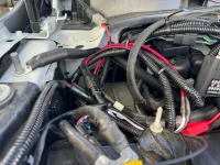
This doesn’t interfere with my hood at all. (But I see a couple zip-ties I forgot to adjust/clip) (This area is a mess right now because I have coiled and secured the compressor wiring I haven’t routed and connected yet.)
 

Attachments

  • IMG_1159.webp
    IMG_1159.webp
    220.9 KB · Views: 104
How did you accomplish this. When using that post seems my hood is not closing correctly and leaves a gap.
You can run the ground cable towards the outside of the engine bay, down, and around the support the ground post is threaded into. Then it won’t interfere with the gas strut for the hood.

Personally, I found it a lot easier to attach it to one of the large ground nuts against the firewall.
 
This doesn’t interfere with my hood at all. (But I see a couple zip-ties I forgot to adjust/clip) (This area is a mess right now because I have coiled and secured the compressor wiring I haven’t routed and connected yet.)
I may certainly be wrong but it appears the gas strut has left an indentation in the ground cable.
 
Back
Top Bottom