That’s not really how DC systems work. Technically electrons flow out the negative terminal and into the positive terminal, not the other way around. The term “ground” isn’t the same as an AC system.
It’s very difficult for an ECM to monitor current directly because it’s not connected directly to every circuit and that would require a lot of heavy gauge copper. Control circuits with low current (small wires) trigger power circuits (big wires) via relays. It would be a lot easier to measure voltage but unfortunately that is a lousy indicator of battery performance. Enter the current transformer, but where to put it?
It’s easier/cheaper to monitor the ground path because that is a common reference for every circuit. While there are only 2 wires coming off the battery ground, they are actually carrying all the power coming out of the battery!
Which leads me to another point. Wire sizing isn’t just about current but about length and continuous draw (time). You will notice the surprisingly small gauge wires from the battery to the chassis (going through the CT). That’s because the run is very short. The chassis is a giant conductor with many small arteries connected at various points. It can handle a lot of current. The ground wire and lug used in this harness looks really oversized.
The theory here is correct with a few caveats related to our trucks. I believe we are overthinking this sensor and its purpose. I admit, I got caught up in it as well until I read the manual.
The sensor is what is called a Hall Device, basically a DC current sensor without direct connection to the circuit. AC/variable current would typically be sensed through a transformer or tap. I believe the Hall device is merely monitoring the state of charge from the alternator/generator. The alternator converts AC to DC and then is fed to the batteries as a DC, to regenerate a charge. It's also (obviously) to run the vehicle accessories while in operation. The current connection path is through this sensor.
The Hall device can sense both negatively flowing, and positively flowing current. It is a sensor to determine charge or discharge, which is fed to the BCM to determine health. Most all of the DTCs related to this device are also related to generation troubleshooting tips. (In the maintenance section of the complete manual.)
As for the hook-up in the truck, it would not be necessary to run any cables through this sensor for operating any added accessory. Using the chassis ground is sufficient and frankly, does not directly determine state of charge with generation. To emphasize this point, if you have dual batteries, only one battery is hooked up through this sensor. And there is good reason. The other battery is connected directly to the engine block, which makes it electrically the same as the chassis. The current generated by the alt/generator will be felt for both batteries while charging, through this sensor, since the chassis and engine block are electrically at the same point.
Here's an excerpt from the manual:
Battery Current Sensor
The battery current sensor which only monitors current flow in/out of the battery, The battery current sensor is attached to the battery negative
cable. It is supplied a 5-volt reference voltage and a ground from the BCM. The battery current sensor is a Hall-effect sensor that supplies an
analog feedback signal to the BCM. The BCM reads the battery current sensor feedback voltage to determine how much current is flowing
through the battery ground cable. The BCM uses this information for battery state of charge.
One more tid-bit from the manual:
PINPOINT TEST I : BATTERY CURRENT SENSOR FAULTS
Refer to Wiring Diagrams Cell 12 for schematic and connector information.
Normal Operation and Fault Conditions
The BCM monitors the battery state of charge using the battery monitoring sensor attached to the negative battery cable. Battery voltage is hardwired to the battery monitoring sensor and data is transferred from the battery monitoring sensor to the BCM via a LIN circuit.
DTC Fault Trigger Conditions
DTC Description Fault Trigger Condition
BCM
B11DB:02...
...and a whole lot more troubleshooting points after this related to charging DTCs.
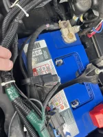
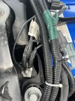
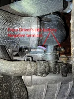
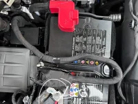
Here are some schematics showing the electrical position of the sensor. Schematic 2 does not show the sensor, but it is connected around the two wires showing connection to the chassis/negative battery post of only one battery. (Passenger side) The other negative terminal is hooked directly to the engine block.
I hope this helps clarify, bottom line: Hook the upfitter ground cable directly to the chassis or whichever negative battery stud that's convenient.









![What did you do to your Tremor today? [2019-2024]](https://www.fordtremor.com/data/files/featured_images/featuredimages_thumb_6.webp?1790518609)


