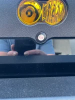
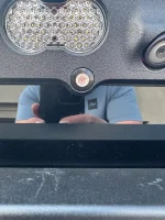
Swarf Works 3rd Brake Light W/Starlink

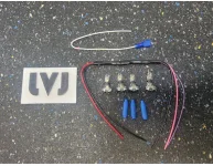
I thought I would post the kit I bought for the running lights.


They should be delivered today. I am hoping to have them installed this week.


Here is a video explaining most of the wiring. I’m going to talk through it with Kieth from LVJ. I will take pictures and post them once I’m done.

 
Please feel free to reach out to me when you are ready. I am mostly done. I have a couple other options for accomplishing the end goal. I can’t imagine the wires being any more difficult to find.

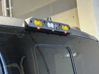
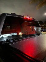
The S2s are functional. Once I get the remaining parts everything will operate how I planned. The cargo light will function as OEM and will also come on with Aux 6 which is tied to the reverse lights. The reverse lights come on with Aux 6 or putting the truck in reverse. Amber S2s are wired to Aux 5. Once I get the remaining parts everything the 3 red LEDs will function as running lights like the Raptor and as a 3rd brake light. I am almost to the finish line.

I seriously cannot thank @Baja Designs , Paul from Swarf Works and Arod PTT for helping me with this project. I couldn’t be happier with the result.
What did you use to black out your license plate? 🤪
 
My god given artistic abilities. If you are wondering if I can teach you, the answer is no. God did not find you worthy bestow these amazing gifts upon you. 🤣
 
Last edited:
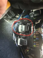
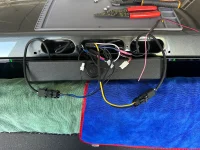
Ok so I was able to accomplish the BCM tap and installation of the LVJ 3rd brake light harness. It should all be working properly. However, the center LED on the SWARFWORKS light is different than the other 2. As you will see in the picture below it works perfectly with 2 lights. I’m waiting to hear back from Paul. Keith from LVJ was awesome! He went completely out of his way to coach me through the whole process. I truly felt bad for how many questions I had.

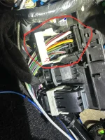
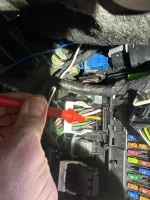
As far as location of the correct wire at the BCM. It took about 45 minutes to figure out which was the correct wire. I first had to figure out how to remove the cover to the wire. Then I removed the plug from the BCM. Ensure the vehicle is off. Once I removed the plug I was able to remove the cover. I also removed some of the electrical tape to better expose the wires. Then I proceeded to ground the negative of the voltmeter. I used the grounding nut and loosened it up to where I could hand tighten it down keeping it in place. That allowed me to only manage the positive. Kieth recommended using a sewing needle to make better access. I unfortunately did not have one on hand. I was able to stick my volt meter in between the wires and test with the parking lights on and off looking for the correct wire. It should be about 12.45 volts with the parking lights on then 0 with them off. Once I located the correct wire I used a wire tap.

Adapting the harness was another task. Keith advised me to cut the harness by the S2s. Then splice both blue and yellow wires together and use the single yellow wire for both amber S2s this was the tied into a pass through wire and added to Aux 5. This freed up the blue wire to be used for the wire tap at the BCM and the purple/blue wire of the LVJ 3rd brake light harness. The pink wire from the harness get tapped into the positive of the factory 3rd brake light harness from the truck. The Black from that side goes to the black from factory harness. The other end of the LVJ 3rd brake light harness is a positive and a negative wire. These go to the SWARFWORKS harness for the 3 red LEDs. My wires are black but I was able to follow from the ford wires. I tapped these on the extension in case I screwed up.

I hope this all makes sense. Please feel free to hit me up with any questions. I will update the thread as I get more information.
 

Attachments

  • IMG_4497.webp
    IMG_4497.webp
    225 KB · Views: 79
  • IMG_4498.webp
    IMG_4498.webp
    188.2 KB · Views: 64
  • IMG_4499.webp
    IMG_4499.webp
    301.8 KB · Views: 63
  • IMG_4500.webp
    IMG_4500.webp
    232.4 KB · Views: 65
  • IMG_4501.webp
    IMG_4501.webp
    589.5 KB · Views: 73
  • IMG_4503.webp
    IMG_4503.webp
    113.5 KB · Views: 76
Additionally if I was to do it over, I would have purchased the harness that has Aux and reverse. This would make a cleaner installation. It would make it so you have a dedicated wire run for the running lights instead of having to splice the amber S2s. When I add the star link I might replace the entire harness to make it perfect.
 
@Terryw123 that's great news and similar to what Keith advised me. When I texted him I realized I had previously spoken to him back in 2020 when I put a GJ 3rd brake light on my first Tremor, he was equally helpful. My brake led harness is on its way from him and I will revise my install in the same way. I see you have a 20 but for any of you with a 24 here is the attached BCM pin and wiring diagram supplied from @BroncOh which was incredibly helpful. I used C2280C pin 3 for the reverse/cargo harness, and will likely use pin 10 for the running lights when I install the harness. Hope this helps someone.

BTW, I am interested to hear what Paul shares on the center LED situation, all mine work now but may not per your experience once I turn them into running lights as well.
 

Attachments

It may be easier to do the splice(s) in the wire trough under the sill scuff plate instead of the small access at the BCM, which requires a contortionist on site. The wire color should be the same as at the connector. There are some similar colors, so the best way is to use a needle and a voltmeter to confirm the correct wire/stripe color combo and then mark it with a Sharpie. I found mine easily by using the fob and hitting the lock and unlock buttons.
 
Ok I spoke with Paul at SWARFWORKS. Turns out that there are a couple center lights that have a higher resistance which is why it’s not working. He immediately shipped me a new one that I am willing to swap on my own. He also offered to have me ship it to him so he could do the work.

As soon as I receive it and reinstall everything I will update again. I completely recommend doing this. It looks great in the picture but even better in person. If I can do this any one can.
 
I'm hoping someone on this thread can help me figure out a solution for how I want to mount the Starlink to my truck.

I want to use the following mount and prefer to retain the OEM brake light or the solution developed in this thread would be the way to go.


What I'm not crazy about is that the mount requires that you either use a window passthrough to get power to the dish or run the wire through the ceiling and then break the seal to the cab to get the wire up to the dish. The latter would be a cleaner install, but lead to concerns on water intrusion into the cab.

The mount I want to use is compatible with the Bulletproof Diesel Third Brake Light Dual Antenna Mount (apparently they plan to make one compatible with the single antenna mount in the future).

I talked to the folks at Bulletproof Diesel (BPD) and they are suggesting I use this mount with the power passthrough:


The downside of this mount is that it has the power pass on the bottom rear facing side, between the added auxiliary lights. This would then require splicing a power cable to work with the Clinko port. Not an ideal solution as then I'd have a plug with a cable I'd then have sticking out from the mount. Not as clean of an install as I'd like.

The team and BPD mount the full size dish for their Baja trucks and use Power over Ethernet (PoE) to power the dish, something that isn't possible to do with the mini.

I was wondering if there would be a way to replace one of the NMO connectors on the regular dual antenna mount to run power through there. The BPD rep advised it can be removed, but is unsure if the cable can be run through the opening and then there is the issue of water intrusion through the opening. Is there something I can use to create a plug that would fit in the NMO mount space? I do plan to use one side for my GMRS antenna.


Ultimately, my goals are to:
- Keep the OEM brake light
- Move the GMRS antenna to the roof
- Mount a Starlink mini and run power through the cab in a way that prevents water intrusion
- Minimize visible wires or plugs where possible.
 
I’m sure there will eventually be more products available. I haven’t seen anything else that meets your needs. Honestly the SWARFWORKS is the only clean way to do it that I haven’t seen anything seen.

As I’m writing this I was thinking another option would be a roof rack. It would give you a more useful investment and good mounting options for lighting.
 
Ok I spoke with Paul at SWARFWORKS. Turns out that there are a couple center lights that have a higher resistance which is why it’s not working. He immediately shipped me a new one that I am willing to swap on my own. He also offered to have me ship it to him so he could do the work.
Good morning @Terryw123
I sent you a PM yesterday wondering if you have a phone number or other contact info for Paul at Swarfworks. My light has been delivered but one item was incorrect and I am trying to get in touch with him to exchange it. I have emailed him several times and filled out the contact info on the website. I am trying to get this installed before the Waco meet-up next month. Thank you my friend!
 
Last edited:
Suspect maybe they’re just a bit slammed with the popularity of it. At least I assume popularity as he’s has to start taking preorders again.

Reached out a couple of days ago as well via contact and am still waiting on a response. Figure may as well ask here from the people who have it so I maybe don’t have to wait. Haha

If you order the Starlink mount with NMO, do you get two mounting points always, meaning you get two of the cable lengths requested, or is it just the single mount and/or cable?
 
Suspect maybe they’re just a bit slammed with the popularity of it. At least I assume popularity as he’s has to start taking preorders again.

Reached out a couple of days ago as well via contact and am still waiting on a response. Figure may as well ask here from the people who have it so I maybe don’t have to wait. Haha

If you order the Starlink mount with NMO, do you get two mounting points always, meaning you get two of the cable lengths requested, or is it just the single mount and/or cable?
If you order the Starlink mount you will get 2 of the extension length cables if you purchase them. There will 2 NMO mounts.
If not, you can purchase them separate.
You can look at the pictures I posted and see the connections which is approximately 12inches in length.
 
If you order the Starlink mount you will get 2 of the extension length cables if you purchase them. There will 2 NMO mounts.
If not, you can purchase them separate.
You can look at the pictures I posted and see the connections which is approximately 12inches in length.
Awesome. That’s what I figured, but it wasn’t spelt out directly for me, and wanted confirmation before I started thinking about ways to get it north of the border. Haha

Thanks!
 
If you order the Starlink mount you will get 2 of the extension length cables if you purchase them. There will 2 NMO mounts.
If not, you can purchase them separate.
You can look at the pictures I posted and see the connections which is approximately 12inches in length.
Hey @JayTremor, second follow-up on this; got my name on the list for an upcoming batch, definitely leaning to this for my NMO mounts rather than doing the A-Pillar//Hood style.

Seeing a few more videos and photos of it now, I'm seeing that the Starlink power connector seems to be integrated in, and SW puts the connector into the mount and through for you to just attach your power too; is there anything there in the other side that would make you think one could potentially feed the ethernet cable through the mount too? From photos and videos, it looks like the recess is there for the cable connector (in theory), but it seems solid without any passthrough...

Snap off the locking tab from the end of the ethernet so it doesn't lock in place, then hopefully that would insert/remove just like the power, and terminate the other end inside the cab (or somewhere else), and have a hardwire port that you could then use with another router, longer cable, etc to expand the WiFi capabilities, or even just hardwire your laptop or device in times where the WiFi from the Mini might be drowned out...

Too many thoughts, not enough time, money, or skill to implement...
 
Well I am finally done!! It works perfectly!

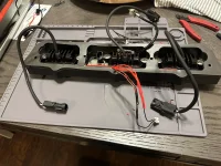
So as an update from my previous post. You can see that there is a difference in the LEDs that came with it. Normally I would have never noticed as they were identical when the brake was applied. However the two outside LEDs operate at a lower resistance not allowing the center light to activate. Paul helped me figure out this issue. I felt comfortable removing the LEDs. I chose to solder the wires together because the wires are so small. Then I used heat shrink to cover the joints. Everything went in very easily.

Additionally, I am not sure I’m not sure that I mentioned before. For the LVJ 3rd brake light harness the instructions are to tie into the positive and negative of the SWARFWORKS LEDs. I was originally cautious about doing this. So I tapped into the adapter on the positive and negative. I think it worked out better.

I hope everything I have posted makes sense. Please feel free to hit me up with any questions as I have literally taken apart and rebuilt the entire light.
 

Attachments

  • IMG_4538.webp
    IMG_4538.webp
    136.5 KB · Views: 77
  • IMG_4537.webp
    IMG_4537.webp
    227.8 KB · Views: 78
  • IMG_4536.webp
    IMG_4536.webp
    352.1 KB · Views: 70
  • IMG_4535.webp
    IMG_4535.webp
    379.2 KB · Views: 82
Last edited:
Well I am finally done!! It works perfectly!

So as an update from my previous post. You can see that there is a difference in the LEDs that came with it. Normally I would have never noticed as they were identical when the brake was applied. However the two outside LEDs operate at a lower resistance not allowing the center light to activate. Paul helped me figure out this issue. I felt comfortable removing the LEDs. I chose to solder the wires together because the wires are so small. Then I used heat shrink to cover the joints. Everything went in very easily.

Additionally, I am not sure I’m not sure that I mentioned before. For the LVJ 3rd brake light harness the instructions are to tie into the positive and negative of the SWARFWORKS LEDs. I was originally cautious about doing this. So I tapped into the adapter on the positive and negative. I think it worked out better.

I hope everything I have posted makes sense. Please feel free to hit me up with any questions as I have literally taken apart and rebuilt the entire light.
Awesome man. Hope my brother, @Rodd187 sees this and pulls it off. Looks great.
 
Awesome man. Hope my brother, @Rodd187 sees this and pulls it off. Looks great.
Thank you brother for the tag, following this intently. Now I just need the brake housing to show up in time for Waco.
 
when did you guys place your order? I'm waiting almost 2 month and delay after delay no replay from the guy at all. Still want it but I can read all over internet customer service is not his priority..Seems like he acquired GJ motorsport's behavior as well..
I’ve been waiting on responses from a couple of emails for awhile now too; he’s definitely swamped it seems, assembling and shipping all this by himself.

I’m close to just pulling the trigger anyway and if it turns out my questions can’t be tackled, then oh well, it still does 95% of what I hoped. Just basically waiting now to finalize my days off so I know I’ll be home to get it when it would arrive. Haha
 
Back
Top Bottom