Hello Everyone,
I have been playing around over the weekend with creating an easy to use plug and play system for connecting auxiliary accessories to the upfitter switches. I wanted a simple solution that provides both power and ground to plug and play auxiliary connectors. Here is what I have created, and I will include the 3D printed files if anyone wants to print one as well, or make any modifications as needed.


The box is printed in 3 parts. The bottom cover, the top cover and the bottom support bar. The bottom support bar is glued and screwed onto the bottom of the box in that small cutout with the two smaller holes.
The box is attached to the top of the passenger side battery tray, utilizing the passenger side 12v battery strap stud. The stud has plenty of length for the bottom tray to slide over top of, and a washer and nut is added to it to bolt the box in place. You can adjust how high or low you want the box by placing a nut on the stud before sliding the box in place. The bottom support bar that was glued and screwed in place slots snugly into the U channel of the battery strap.
The box has 6 cutouts for 2 slot automotive connectors to slot into. You can find a multitude of them on Amazon.
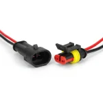
I have designed the box with a paper thin piece of filament blocking each connector hole, to provide dust proofness in case all 6 holes are not being used. When needed, just use your finger to knock out the hole and a knife to clean up the edge. The male end of the connector clips right into the hole.
All 6 upfitter wires can be extended with a 1 foot piece of wire and is brought inside the box through the large hole in the bottom. You can add a grommet or I opted for a firewall busing instead for additional dust proofness.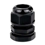
The side of the box facing the battery negative terminal has a hole cut out for a 10 gauge wire. Add a ring terminal to the 10 gauge wire to connect to the battery terminal, bring the other end into the box and crimp it to six 16 gauge wires for the negatives.
Connect one negative wire, and 1 aux wire to each connector and slot them into place in the bottom box. Screw on the top box and you’re done! All future accessories are now plug and play.
I didn’t create this project as a way to sell this product, but just a simple DIY solution to fit my needs. If anybody else wishes to do the same, I have added the 3D printable files to a Dropbox link where you can download them for free and print it yourself. Feel free to do whatever you wish with the files, or modify it as needed to suit your needs. I’ve made a small modification to the top box, I’ve added “Aux 1 to Aux 6” beside each connector hole in the top box.
 www.dropbox.com
I have been playing around over the weekend with creating an easy to use plug and play system for connecting auxiliary accessories to the upfitter switches. I wanted a simple solution that provides both power and ground to plug and play auxiliary connectors. Here is what I have created, and I will include the 3D printed files if anyone wants to print one as well, or make any modifications as needed.
The box is printed in 3 parts. The bottom cover, the top cover and the bottom support bar. The bottom support bar is glued and screwed onto the bottom of the box in that small cutout with the two smaller holes.
The box is attached to the top of the passenger side battery tray, utilizing the passenger side 12v battery strap stud. The stud has plenty of length for the bottom tray to slide over top of, and a washer and nut is added to it to bolt the box in place. You can adjust how high or low you want the box by placing a nut on the stud before sliding the box in place. The bottom support bar that was glued and screwed in place slots snugly into the U channel of the battery strap.
The box has 6 cutouts for 2 slot automotive connectors to slot into. You can find a multitude of them on Amazon.
I have designed the box with a paper thin piece of filament blocking each connector hole, to provide dust proofness in case all 6 holes are not being used. When needed, just use your finger to knock out the hole and a knife to clean up the edge. The male end of the connector clips right into the hole.
All 6 upfitter wires can be extended with a 1 foot piece of wire and is brought inside the box through the large hole in the bottom. You can add a grommet or I opted for a firewall busing instead for additional dust proofness.
The side of the box facing the battery negative terminal has a hole cut out for a 10 gauge wire. Add a ring terminal to the 10 gauge wire to connect to the battery terminal, bring the other end into the box and crimp it to six 16 gauge wires for the negatives.
Connect one negative wire, and 1 aux wire to each connector and slot them into place in the bottom box. Screw on the top box and you’re done! All future accessories are now plug and play.
I didn’t create this project as a way to sell this product, but just a simple DIY solution to fit my needs. If anybody else wishes to do the same, I have added the 3D printable files to a Dropbox link where you can download them for free and print it yourself. Feel free to do whatever you wish with the files, or modify it as needed to suit your needs. I’ve made a small modification to the top box, I’ve added “Aux 1 to Aux 6” beside each connector hole in the top box.







![What did you do to your Tremor today? [2025 edition]](https://www.fordtremor.com/data/files/featured_images/featuredimages_thumb_6.webp?1788323896)


