-
Featured
- #1

I finally have my 2024 F350 King Ranch so time to start with the additions. I needed the 8' bed so it is not a Tremor, but this forum has a LOT more usable information than other Super Duty forums so this is the place!
Already done:
Igla immobilizer installed
Passenger side auto hub on in place of the fixed hub
Line-X is done
Undercover Armor Flex Tonneau Bed cover
Built Right bed molle panels
Built Right drivers side rear seat release
Front windows tinted
2WD valance
To do:
VIAIR on-board air (VIAIR 485c dual system
Carli 3.5" Pintop
Full stereo system
So here is what I am doing for the on-board air...
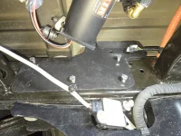
So @Whyte Rhyno has a really good write up on his install of the same system on a 2020 F250 Tremor which is what I am taking a lot of my inspiration from. With that being said once I dropped the spare tire there were immediately some issues apparent, namely a huge wire harness that runs on the driver's side frame rail which is not going to be easily re-located, there simply is not enough slack. There is also a module (no clue what it is) on the passenger side rail, but I already have a plan to move it which shouldn't be difficult at all.
So here is what I am working with...
Macro:

Passenger Side:

Driver's side:

First item that I am going to tackle is what to do about the driver's side to mount that compressor (will be one on each frame rail on either side of the spare tire mount). I am using brackets that are made by VIAIR which are designed to hold the compressors.
Bracket:

With compressor:

The way I have decided to tackle this is to 3D print a spacer which will go over and encapsulate the wire harness on the driver's side frame rail. To design this spacer I am using a 3D scanner, specifically a Revopoint POP 3. Now, in full disclosure today is the first time I have even played with the scanner.... I ordered it on a Black Friday deal while I was still deployed in Iraq just to use for projects like this. I just got home 4/1/24 (am posting this 4/5/24) and today was the unboxing so to speak. I watched several videos while deployed and then watched a few more this morning, and basically put it to work scanning the wire harness/frame rail area. From watching videos on YouTube I already knew that trying to scan a black harness, on a black frame, under the truck and in shadows would be "challenging" and it was. The scanners use lights and a series of cameras to scan, since black absorbs light they are particularly challenged when scanning black objects, and even more so in poor lighting conditions... all of which I was fighting. But I knew this and had a solution. Revopoint makes a white powder like spray that comes in a can, when sprayed on something it looks like white foot powder spray (Tinactin), and just like foot powder spray it eventually evaporates. In this case it evaporates in about 20 minutes leaving absolutely zero residue behind. It is not cheap, but it sure did work!
Scanner:
Spray:
So after using the 3D scanning spray I completed my scan. There are some areas that did not scan due to the tight quarters and not being able to move around to all angles, but I got enough to work with.

I then imported the Mesh STL file into Fusion 360 to work off of start my design.

Once I had the Mesh in Fusion 360, and finally figured out to make the origin plane in Fusion 360 match the orientation of the frame rail (when I first imported it was waaayyyy off, needs to match to begin your first sketches), I was able to go to work. The first order of business was to verify dimensions, I did this by sketching the rectangular opening in the frame rail utilizing the Mesh file, designing a small part that was to fit inside of the rectangle snuggly, and doing a test print out of an inexpensive test material. For the first test print I used PLA, for the actual part I will use ASA as it is strong, chemical resistant and heat resistant... basically an evolution of ABS plastic. PLA is super cheap to print so for mock-ups and test prints it is the material to use, but not suitable for automotive use at all. Bottom line up front, it fit perfectly, like snapped into place.


Already done:
Igla immobilizer installed
Passenger side auto hub on in place of the fixed hub
Line-X is done
Undercover Armor Flex Tonneau Bed cover
Built Right bed molle panels
Built Right drivers side rear seat release
Front windows tinted
2WD valance
To do:
VIAIR on-board air (VIAIR 485c dual system
Carli 3.5" Pintop
Full stereo system
So here is what I am doing for the on-board air...
So @Whyte Rhyno has a really good write up on his install of the same system on a 2020 F250 Tremor which is what I am taking a lot of my inspiration from. With that being said once I dropped the spare tire there were immediately some issues apparent, namely a huge wire harness that runs on the driver's side frame rail which is not going to be easily re-located, there simply is not enough slack. There is also a module (no clue what it is) on the passenger side rail, but I already have a plan to move it which shouldn't be difficult at all.
So here is what I am working with...
Macro:
Passenger Side:
Driver's side:
First item that I am going to tackle is what to do about the driver's side to mount that compressor (will be one on each frame rail on either side of the spare tire mount). I am using brackets that are made by VIAIR which are designed to hold the compressors.
Bracket:
With compressor:
The way I have decided to tackle this is to 3D print a spacer which will go over and encapsulate the wire harness on the driver's side frame rail. To design this spacer I am using a 3D scanner, specifically a Revopoint POP 3. Now, in full disclosure today is the first time I have even played with the scanner.... I ordered it on a Black Friday deal while I was still deployed in Iraq just to use for projects like this. I just got home 4/1/24 (am posting this 4/5/24) and today was the unboxing so to speak. I watched several videos while deployed and then watched a few more this morning, and basically put it to work scanning the wire harness/frame rail area. From watching videos on YouTube I already knew that trying to scan a black harness, on a black frame, under the truck and in shadows would be "challenging" and it was. The scanners use lights and a series of cameras to scan, since black absorbs light they are particularly challenged when scanning black objects, and even more so in poor lighting conditions... all of which I was fighting. But I knew this and had a solution. Revopoint makes a white powder like spray that comes in a can, when sprayed on something it looks like white foot powder spray (Tinactin), and just like foot powder spray it eventually evaporates. In this case it evaporates in about 20 minutes leaving absolutely zero residue behind. It is not cheap, but it sure did work!
Scanner:
Spray:
So after using the 3D scanning spray I completed my scan. There are some areas that did not scan due to the tight quarters and not being able to move around to all angles, but I got enough to work with.
I then imported the Mesh STL file into Fusion 360 to work off of start my design.
Once I had the Mesh in Fusion 360, and finally figured out to make the origin plane in Fusion 360 match the orientation of the frame rail (when I first imported it was waaayyyy off, needs to match to begin your first sketches), I was able to go to work. The first order of business was to verify dimensions, I did this by sketching the rectangular opening in the frame rail utilizing the Mesh file, designing a small part that was to fit inside of the rectangle snuggly, and doing a test print out of an inexpensive test material. For the first test print I used PLA, for the actual part I will use ASA as it is strong, chemical resistant and heat resistant... basically an evolution of ABS plastic. PLA is super cheap to print so for mock-ups and test prints it is the material to use, but not suitable for automotive use at all. Bottom line up front, it fit perfectly, like snapped into place.